Shaders – Part 1: Post-processing
In this series, we will look into what games and game engines do to create those neat graphics effects that add to a game’s realism and/or aesthetics: Effects like water reflections, fog, heat haze, bumpy or glossy surfaces, night vision, toon shading, etc. Most video games, especially 3D games, use shaders to create such effects. Shaders are little programs that usually run on the graphics card. They take graphics information such as 3D data and textures as input and calculate new graphics information as output. In the simplest or most intuitive case, the output can be simply a pixel color.

In part 1 we will look at post-processing shaders. These are shaders that are applied to the rendered image to add additional effects before the final image is displayed on screen. While post-processing happens at the end of the rendering process, it is also conceptually easier to understand than other kinds of shaders. This way we can start with some basic intuition and then build upon it with more and more advanced concepts.
I will be using my educational game engine to create the examples. This engine is written in Kotlin and uses a software renderer, which means that the shaders are not written in a typical shading language like GLSL and executed on the GPU, but are implemented in software and executed on the CPU. This is much less performant and you wouldn’t do that for a modern commercial game, but it makes many things explicit and thus easier to follow that would otherwise be implemented in hardware or in the graphics driver.
A trivial example: Replacing colors
As mentioned earlier, post-processing shaders are conceptually easy to understand. Let’s look at a trivial example: We apply a simple shader to an image to replace the color red with blue. The input image could be any image, like a photo, in which case this would basically be like image processing in programs like Photoshop or GIMP, or like the “filters” in social media apps. In our case it is the rendered 3D scene of a video game to which we want to apply additional effects. The shader takes a single pixel color as input and produces a single pixel color as output. The shader is then executed for every pixel of the image, mapping input color to output color. Modern displays have millions of pixels, so this benefits greatly from parallelism, and normally this would be executed in parallel on the GPU for many pixels at the same time.
Following is the Kotlin implementation of this simple shader. My game engine’s software renderer uses shaders written in Kotlin. In most modern commercial game engines, you would use GLSL/HLSL or some dialect of these, but could conceptually do the same things. The implementation of this trivial shader is very simple: If the pixel at the given position in the framebuffer is red, the post-processing shader returns blue. The same for replacing black with white. By default, it just returns the original pixel color.
class ReplaceColorPostProcessingShader : PostProcessingShader {

    override fun postProcess(
        position: Vec2i,
        framebuffer: Bitmap,
        zBuffer: Buffer2f
    ): Color {
        val (x, y) = position
        return when (framebuffer.getPixel(x, y)) {
            Color.red -> Color.blue
            Color.black -> Color.white
            else -> framebuffer.getPixel(x, y)
        }
    }
}
A slightly more complicated example: Grayscale image
We can replace each color of the original image with gray. This still only requires a single pixel color as input, and is still very simple, but slightly more complicated since we now add some simple calculations. There are different ways of converting a color to a grayscale value; there are even different ways to calculate an average. For this example, we will keep it simple and just use the arithmetic mean of the 3 color channels (RGB). (255, 0, 0) would become (85, 85, 85), for example.
Here is the Kotlin implementation of this simple grayscale post-processing shader.
class GrayscalePostProcessingShader : PostProcessingShader {

    override fun postProcess(
        position: Vec2i,
        framebuffer: Bitmap,
        zBuffer: Buffer2f
    ): Color {
        val (x, y) = position
        val color = framebuffer.getPixel(x, y)
        val mean = (color.r.toUInt() + color.g.toUInt() + color.b.toUInt()) / 3u
        return Color(
            r = mean.toInt(),
            g = mean.toInt(),
            b = mean.toInt(),
            a = color.a.toInt()
        )
    }
}
More than 1 pixel as input: Wave pattern
In this example, we still have a single pixel color as output, but we now use more than one pixel as input. The post-processing shader runs for every pixel, but in each instance it can only change that one pixel. Still, we can allow read access to the whole framebuffer. Let’s use that to make a wave pattern on screen, like what you might see in a survival game when the player character is dehydrated or drunk, or in an underwater scene.
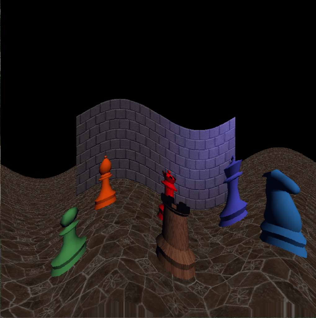
The following code creates such a pattern, more specifically a sine wave. We create 2 full wave periods, scaled by 2 Pi (because the sine function goes “full circle” every 2 Pi), and scale it with the framebuffer width. That’s why, in the image above, you can see 2 full wave periods across the width of the game window.
The amplitude (i.e., the height) of the wave is in this case defined as 5 percent of the framebuffer height. We could, of course, also define a constant height like, e.g., 40 pixels. In this case, it scales with the screen/window size.
Finally, we use the calculated pixel position that we offset vertically by the sine wave, clamp it within the bounds of the framebuffer, and then use it to sample the pixels. Note that in this code snippet clamping is done by Kotlin’s unusually named extension method coerceIn.
class WavesPostProcessingShader : PostProcessingShader {

    override fun postProcess(
        position: Vec2i,
        framebuffer: Bitmap,
        zBuffer: Buffer2f
    ): Color {
        val (x, y) = position

        val periods = 2
        val frequency = periods * (2 * PI) * (1 / framebuffer.width.toDouble())
        val amplitude = 0.05 * framebuffer.height
        val wave = sin(x.toDouble() * frequency) * amplitude
        val sampledY = y + wave.toInt()
        val clampedY = sampledY.coerceIn(0, framebuffer.height - 1)
        return framebuffer.getPixel(x, clampedY)
    }
}
In an interactive video game, we might want to animate that effect. A common way to “animate” shaders is to use the time as an input and use it to manipulate certain parameters.
Here we offset the wave horizontally by the time (in seconds), causing the sine wave to move across the screen every Pi seconds. If we wanted to, we could normalize that by multiplying the time by Pi and then scale it by any arbitrary speed, possibly even based on some in-game state.
Note that the code is written very elaborately here to be easier to follow, but formulas like this are typically considered quite idiomatic in graphics code, so you might see them written much more concisely. Take a moment and try to imagine how the wave behaves when you change certain inputs. What would sin(x * 12 PI + GameTime.frameTime) * 30 do? What would we need to change to get vertical waves?
        val periods = 2
        val frequency = periods * (2 * PI) * (1 / framebuffer.width.toDouble())
        val amplitude = 0.05 * framebuffer.height
        val offset = GameTime.frameTime
        val wave = sin(x.toDouble() * frequency + offset) * amplitude
        val sampledY = y + wave.toInt()
Changing sample position: Pixel art shader
We can simply change which input pixel is sampled per output pixel to create a pixel-art-like effect without even changing any colors (although we could of course combine it with other effects). Unlike changing the render resolution, this gives very sharp pixels as is intended for pixel art and does not use any interpolation for up-scaling to the display resolution.
By (integer) dividing by the size of the “pixels” in the final image and then multiplying by that same number, we sample the same input pixel for multiple output pixels. For example, dividing the pixel position (42, 42) by 4 using integer division yields (10, 10), which multiplied by 4 gives the sample coordinates (40, 40). As usual, there are multiple ways we could do this. We are sampling a corner pixel of each of the “pixel” squares, but we could sample any pixel within each 4x4 square as long as we do so consistently, or we could calculate the average color within each square. Each of these options will look slightly differently and may have different performance characteristics.
val pixelSize = 4
val (x, y) = Vec2i(
    position.x / pixelSize * pixelSize,
    position.y / pixelSize * pixelSize
)
return framebuffer.getPixel(x, y)
Multiple input pixels per output pixel: Blur
We can create a simple blur effect by averaging adjacent pixels. There are many ways to implement a blur shader, some of which have much better quality than this simple one, but here we focus on the general concept with a very simple example. Unlike the earlier examples which only used a single pixel as input, changing either the color or the position from which the pixel was sampled, we now reached a point where each resulting pixel color is a function of multiple input pixels.
This trivial implementation simply calculates the average color of neighboring pixels using bilinear interpolation. In computer graphics and game programming this is also known as bilerp (bilinear interpolation). We interpolate between 4 pixels around the current pixel position (actually in this case we skip one rather than using the direct neighbor, resulting in a slightly stronger blur effect). Each of the four pixel positions is clamped within the framebuffer to prevent out-of-bounds errors when calculating the pixels at the screen borders.
class BlurPostProcessingShader : PostProcessingShader {

    override fun postProcess(
        position: Vec2i,
        framebuffer: Bitmap,
        zBuffer: Buffer2f
    ): Color {
        fun clampInBuffer(position: Vec2i) = Vec2i(
            position.x.coerceIn(0, framebuffer.width - 1),
            position.y.coerceIn(0, framebuffer.height - 1),
        )

        val p1 = clampInBuffer(position + Vec2i(-2, -2))
        val p2 = clampInBuffer(position + Vec2i(2, -2))
        val p3 = clampInBuffer(position + Vec2i(2, -2))
        val p4 = clampInBuffer(position + Vec2i(2, 2))

        return Color.lerp(
            Color.lerp(framebuffer.getPixel(p1.x, p1.y), framebuffer.getPixel(p2.x, p2.y), 0.5f),
            Color.lerp(framebuffer.getPixel(p3.x, p3.y), framebuffer.getPixel(p4.x, p4.y), 0.5f),
            0.5f
        )
    }
}
We intentionally use a very simple implementation here to explain the general concept. For better quality, possibly at some additional performance cost, we could improve this by interpolating between all surrounding pixels including the current pixel, i.e., 9 in total, or even a larger square or approximate circle of pixels around the current position. This is known as a box blur, a simple real-time appropriate blur algorithm.
We could also apply different weights to the surrounding pixels depending on the distance from the current pixel, e.g., using a relative weight of 1 for the current pixel, 0.5 for each of the direct neighbors, 0.25 for each of the second neighbors etc. This results in a smoother blur effect and reduces visual artifacts like double images. We could change the strength of the blur effect by adjusting the weights and/or the size of the area influencing each pixel. When using larger areas for very strong blur effects, we could skip pixels (as we are doing in the above code snippet) to limit the performance impact.
More inputs: Depth
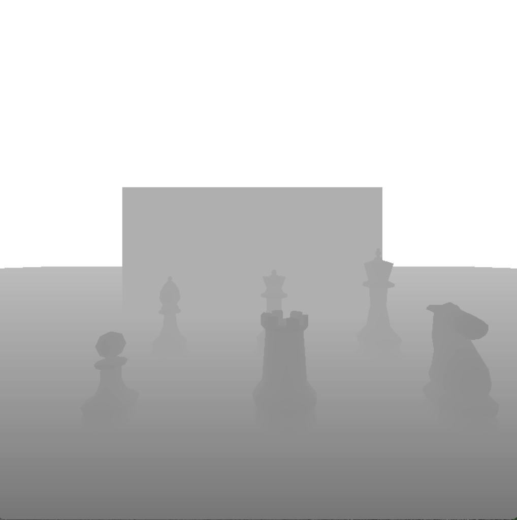
Let’s go one step further and use additional inputs besides the pixels in the framebuffer and the current time. It is common to have access to things like the depth (i.e., the z coordinate) at the current (or any other) pixel position. Similarly to how we can access the color of any pixel within the framebuffer, we can access the depth at any given pixel position via the so called depth buffer or z-buffer (named after the z coordinate, i.e., depth), where each value basically represents the (virtual) distance from the screen or from the player’s eyes. (There is some nuance to how the coordinates may be distributed along the z axis, but here we assume a linear z-buffer for simplicity.)
Although information about the 3D scene (meshes, polygons, world coordinates) is typically not available any more at the post-processing stage, things like the depth buffer are created in earlier rendering stages (we will look at how that works later on in the series) and are then made available for post-processing. Similar to the framebuffer, which contains the pixels of the rendered scene, the z-buffer is basically a grayscale texture where smaller values (black/dark gray) represent closer distances and higher values (white/light gray) represent further distances.
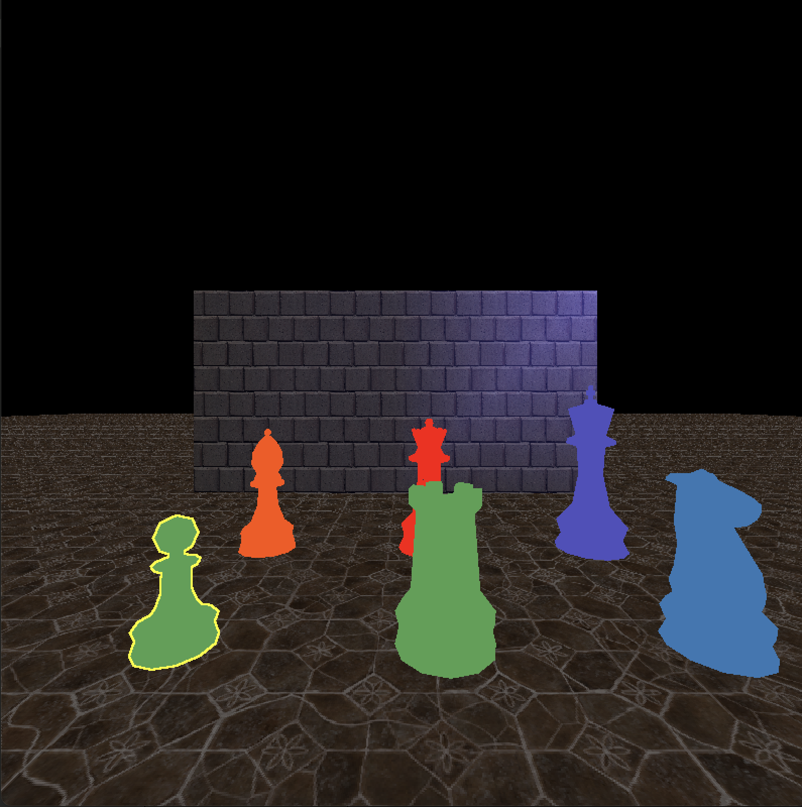
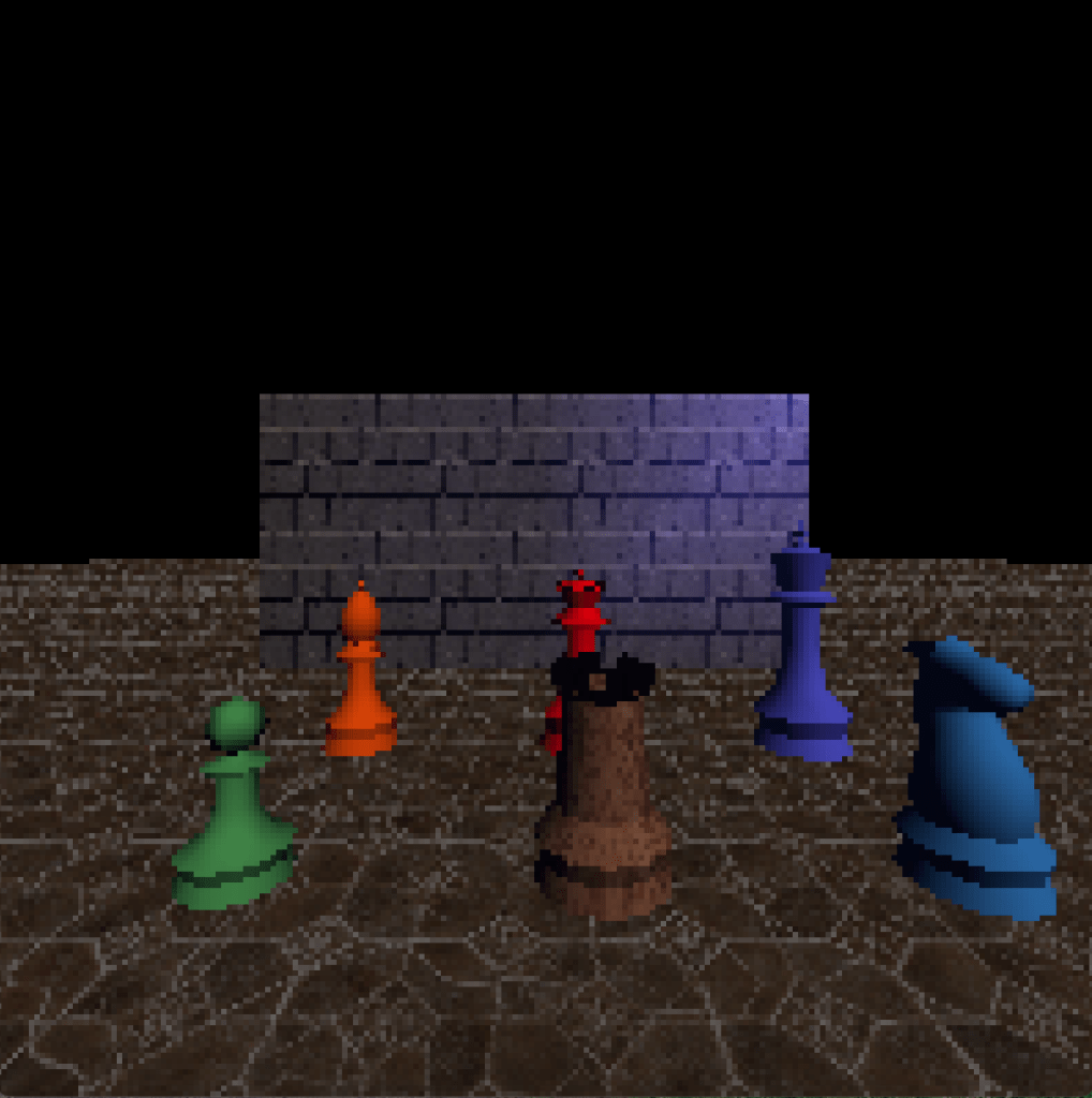
By comparing the depth at the current pixel with the depth at neighboring pixels, we can determine the edges of objects and color those pixels to outline those edges, similar to a cartoon. You’ve probably seen this many times in different games, whether it was to mark the player’s current selection or because of a special ability that marks enemies through walls (maybe even as a cheat).
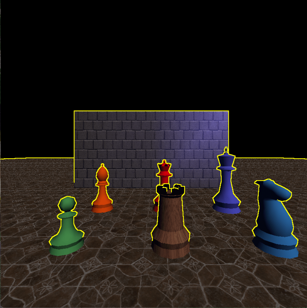
A limitation that you can see in this picture is that the front/bottom edge, where an object touches the floor, is not outlined. This is because the difference between the depth values is basically 0; they literally touch the floor, after all. One way we could fix that is to render the objects that we want to outline to a separate texture, like a z-buffer specifically for one or multiple objects. That way we would also have more control over which objects we want to outline, and we could even use it to outline objects behind walls where the standard z-buffer wouldn’t have any information about them since it contains the closest depth at that pixel. Modern games often render (parts of) the scene multiple times per frame, with different subsets of objects or materials and rendering different properties (colors, depth, lighting information, etc.), but at the cost of additional complexity and computation resources.
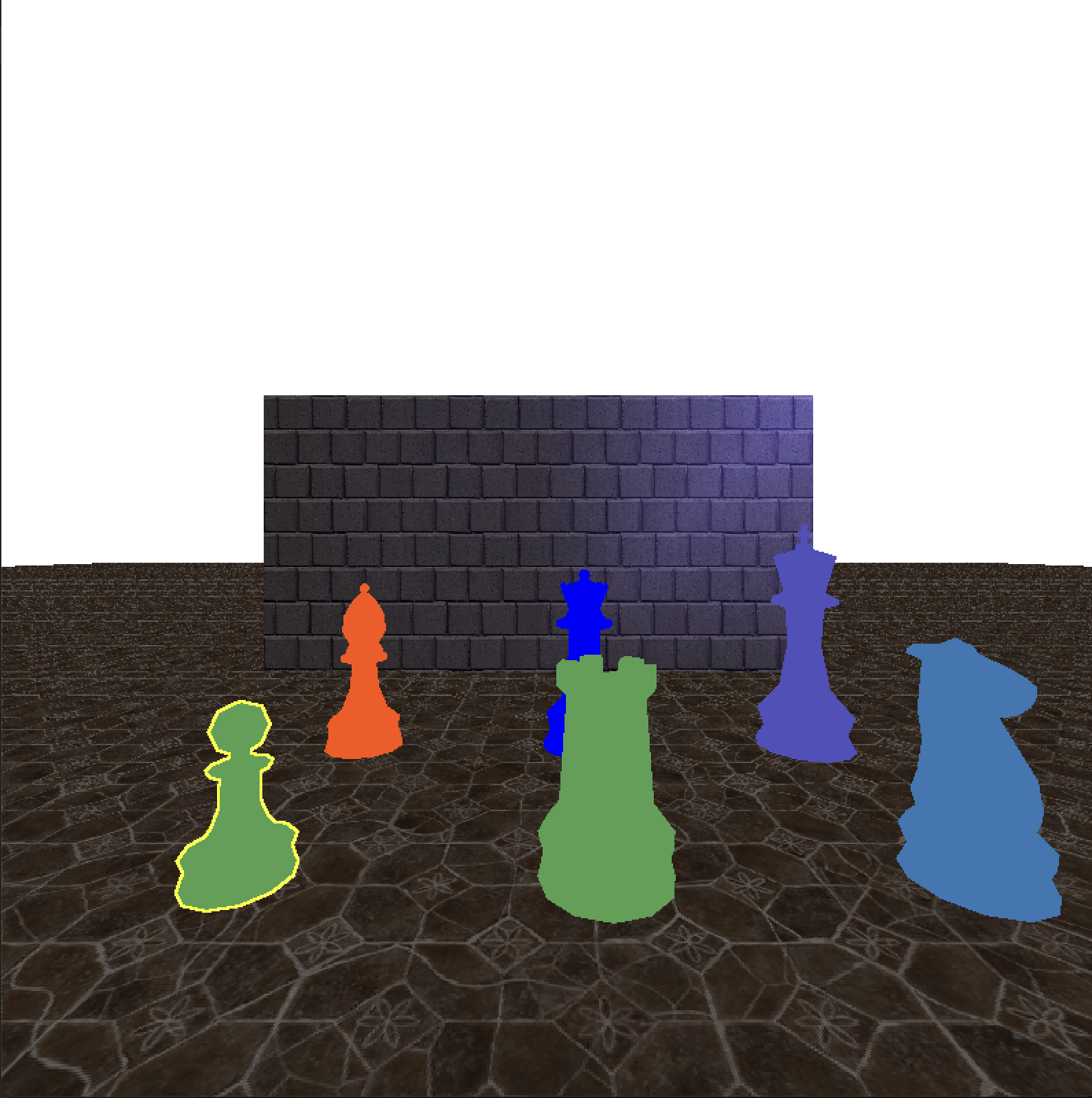
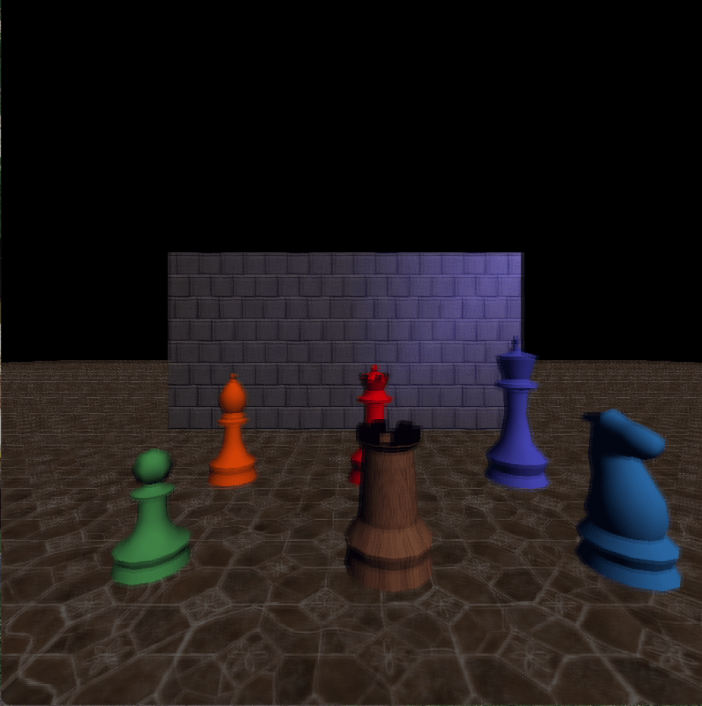
Another example using the z-buffer: Let’s say we want to darken each pixel based on the distance from the camera. It almost looks like we’re holding a torch or flashlight, but we didn’t add any lighting to the scene, it is purely done in post-processing on a per-pixel basis.

Leaving out the boilerplate class and method definitions now, here’s how we might implement such an effect. Try to visualize how changing some of the constants (which we could parameterize if we wanted to) affect the outcome.
val (x, y) = position
val color = framebuffer.getPixel(x, y)
val zBufferDarkening = 40 * (1f - zBuffer.get(x, y)).pow(4.2f)
return color * zBufferDarkening.coerceIn(0f, 1f)
The 1 - z is done to invert the depth values, because we want to darken the areas that are far away. 0 is black, 1 is white. Imagine multiplying (255, 255, 255)rgb by 0, for example. Note that the depth values in the z-buffer are often not mapped linearly in order to get a better resolution closer to the camera, so the depth that is halfway between the camera and the maximum distance might actually not be represented by 0.5, but we won’t go into the details here.
The factor 40 in this case is kind of arbitrary. Without it, the result was just very dark. A value of 0 is literally pitch black, and depending on the maximum depth mapped in the z-buffer, the z-buffer resolution, and the curve on which the depth values are mapped, even objects that are only 5 units (think meters) or so away might still be very dark.
The pow(4.2f) is just an arbitrary exponent to get a nicer polynomial cut-off where the bright depth fades into darkness. We could use different exponents and see what looks good, or even change it dynamically based on some in-game state. In this case, I just tried a few values and then chose this one because I liked the result.
With these last two examples (depth and blur) in mind, can you imagine how a depth of field effect could be implemented? That’s the effect where the thing in focus (often whatever is in the center of the screen) is sharp and everything closer or further away is blurred. As an easier start, how would you blur the image so that things close to the camera are sharp but everything further away gets more and more blurry based on distance?
Randomness, depth, time, color: Night vision shader
In many FPS or stealth games the player can use night vision goggles to see in the dark during secret missions. These night vision goggles typically create a very green-heavy and noisy image where dark areas appear brighter and bright areas (like lights) appear glaringly bright. Let’s create the night vision shader step by step.
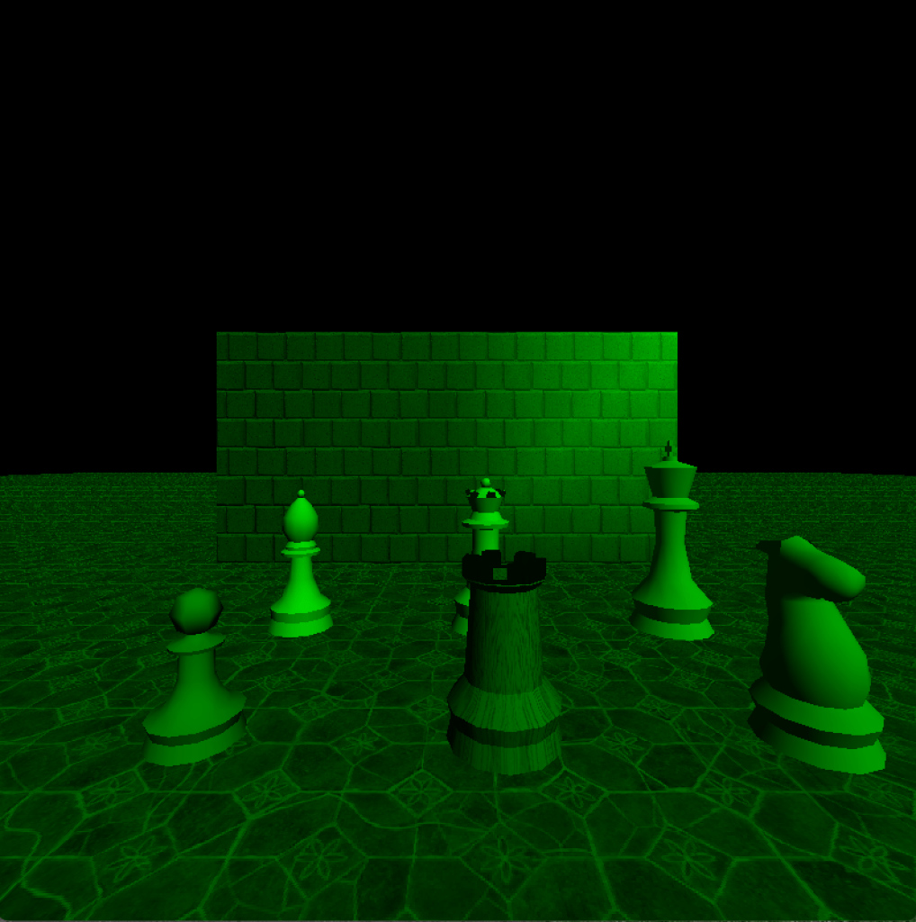
First we want the image to appear green, similar to how we created a grayscale shader earlier. We basically multiply each grayscale value by the color green. As mentioned earlier, there are many ways a color can be converted to grayscale. This time, let’s simply use the maximum value of the three color channels, i.e., max(R, G, B). This is an alternative to using the average, with slightly different results. Since my engine stores colors as unsigned integers, with each channel represented by an unsigned byte, we need to normalize it before multiplying the color green by the brightness per pixel. Here is the result where everything appears green:
And here is the Kotlin code that results in the above image:
val (x, y) = position
val (r, g, b) = framebuffer.getPixel(x, y)
val brightness = listOf(r, g, b).max().toFloat() / 255f
return Color.green * brightness
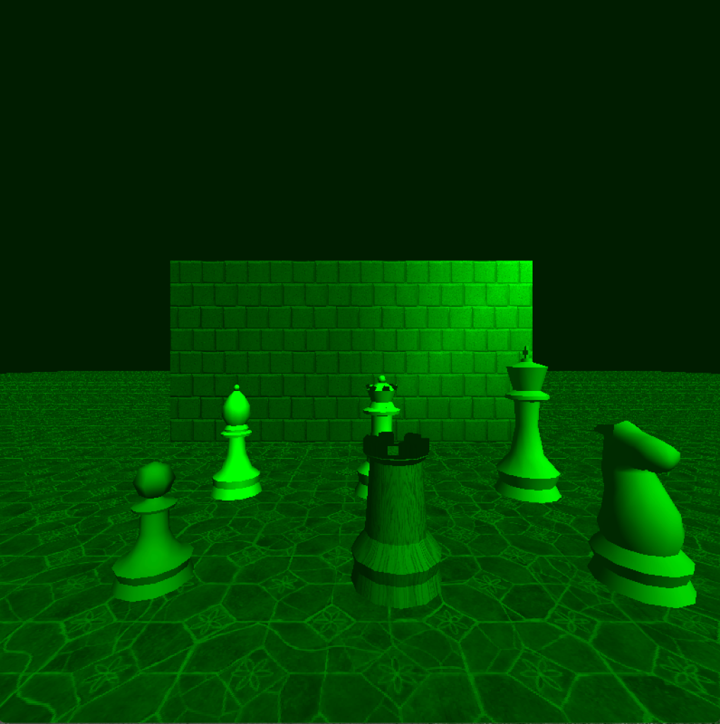
Next, we add some additional brightness to the image as a whole (including the very dark areas, it is night vision after all) and increase the contrast between bright and dark parts of the scene to make already bright areas glaringly bright. This gives as the following result, where the previously black areas are now dark green and bright areas are very bright:
val (x, y) = position
val (r, g, b) = framebuffer.getPixel(x, y)
val brightness = listOf(r, g, b).max().toFloat() / 255f
return Color.green * (brightness + 0.3f).pow(1.8f)
Now let’s add some noise. We simply multiply each pixel by a random value between 0.8 and 1.2. The range of the final pixel is automatically clamped between 0.0 to 1.0. By using a random range around 1.0, the overall brightness is kept the same as without the noise, whereas a random range between, e.g., 0.6 and 1.0 would darken each pixel on average. Although it is not visible in the screenshot, the random noise is calculated every frame, resulting in a white-noise-like effect similar to an old television without signal.

Here is the new version of the night vision shader with added noise. 0.8 is the minimum value and 0.4 is the range, resulting in random values between 0.8 and 1.2.
val (x, y) = position
val (r, g, b) = framebuffer.getPixel(x, y)
val brightness = listOf(r, g, b).max().toFloat() / 255f
val noise = 0.8f + Random.nextFloat() * 0.4f
return Color.green * (brightness + 0.3f).pow(1.8f) * noise
Depth, time, more math: Sonar effect
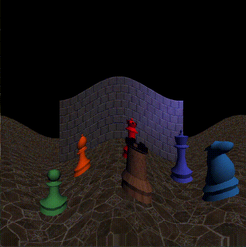
Let’s say we want to add a sonar ability in our game that scans the environment for enemies, items, etc. In some games, this looks similar to the effect shown below: Waves of light or sound being emitted from the player. Although we are doing this in post-processing, the depth information of the scene is used so that the effect is not just “added” on top of the image. See how it moves across the floor and the wall and how it moves through the chess pieces.
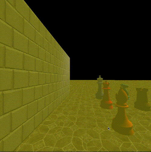
To achieve this effect, we again use the clock time and manipulate it how we like. By the way, frameTime is the time (in seconds since the start of the game) at the beginning of the current frame, because if we took the current elapsed time at the time the shader runs, it would vary for each pixel, which could be noticeable at lower frame rates.
First, to make it periodical, we use the modulo operator. We use time % 1.0 to get the sub-second part, thus slicing the time into nicely normalized chunks of 1 second each.
Since the z-buffer values are not linear but have a higher density closer to the camera than far away (and we do not linearize the z-buffer values here to keep it simple), this would result in the sonar wave moving very slowly while it is close to the camera, and it would start exactly at 0 depth. So instead, we offset it a bit by, e.g., 0.4 and scale the (periodic, sub-second) time to the remaining range of 0.6. This results in sonar waves starting at z = 0.4 and moving towards z = 1.0 within a second. Scaling or mapping a range of normalized values (0.0 to 1.0) to another range (like here 0.4 to 1.0), or vice versa, is also called remap. While the formula might look a bit daunting at first if new to math, graphics/game programming, and/or programming in general, the form a + x * (b - a) is typically considered quite idiomatic and once you’re used to it you recognize it immediately. Even the “magic numbers” would in cases like this generally be recognized as “arbitrary, but chosen experimentally” and their semantics are clear from the context of the remap formula (i.e., range min and max, time scale, etc.). However, feel free to extract additional constants or named variables if you’re still building the intuition. Note that for someone who is used to these common formulas, multiple lines of variables and constants (possibly with long names) are often far less readable, because such an expression as written can be parsed as a whole. It’s different from “uncommon” or situational formulas, where I am all for adding additional names and comments as appropriate.
The resulting sonar waves still expand a bit fast, so we can “slow them down” by scaling the time. 0.5 looked good to me, but again we can experiment with that.
Finally, we limit the waves to the maximum range of 0.8, because 1.0 would be infinite (or at least the maximum visible range), so that the waves are only visible on objects in the scene but not on the skybox (or here the black background). This, again, is an arbitrary visual design decision.
To color the pixels that are currently effected by the sonar wave on the current frame, we interpolate between the current pixel color and the color yellow, with an arbitrarily chosen weight that slightly favors the original pixel color.
val (x, y) = position
val color = framebuffer.getPixel(x, y)
val depth = zBuffer.get(x, y)
val currentSonarDepth = 0.4f + ((GameTime.frameTime * 0.5f) % 1f) * 0.6f
if (depth in currentSonarDepth..0.8f) {
    return Color.lerp(color, Color.yellow, 0.4f)
}
return color
Conclusion
That’s it for part 1, “Post-processing”. Which other effects would you be able to create now based on the examples above? Which effects from games you’ve played do you understand better now?
We started with post-processing, since it is relatively easy to understand compared to other rendering techniques if you’re new to graphics programming. We will build onto this understanding in the upcoming parts where we will look at how objects in the scene are rendered using different materials and textures, normal mapping, vertex and fragment shaders, lighting, transparency, reflection and refraction, and more, some of which use techniques similar to those we’ve seen above.